AR Tracking
Tracking edges are necessary to start the superimposition of the ghost model at the beginning of the inspection. They serve as references for the matching process in the SuPAR App.
At least 60 % of the tracking edges must match the real product; otherwise the tracking operation cannot be started.
Select camera positions
- Position: Adjust the camera position. The default position is above the CAD model. The camera position is set so that the edges are extracted from the side where the inspection will be performed.
- Reset: Reset the camera to its default position.
- Scroll: Adjust the camera field of view. The field of view is adjusted based on the edges to be extracted.
Edge extract
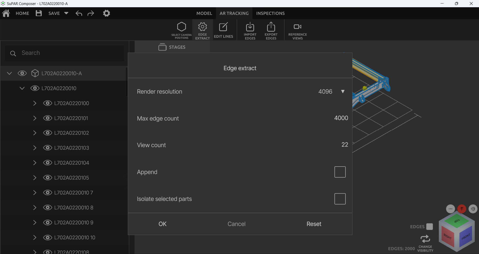
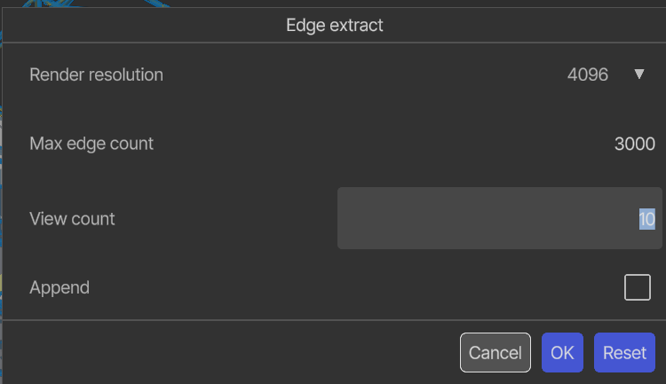
- Render Resolution: Edge extraction precision. Set it higher for more precise edge extraction.
- Max Edge Count: Limit the maximum number of edges. Increasing the limit does not extract more edges for each part — it depends on the edges present in the CAD model.
- View Count: Number of cameras used for the edge extraction. Set it higher to get more tracking edges.
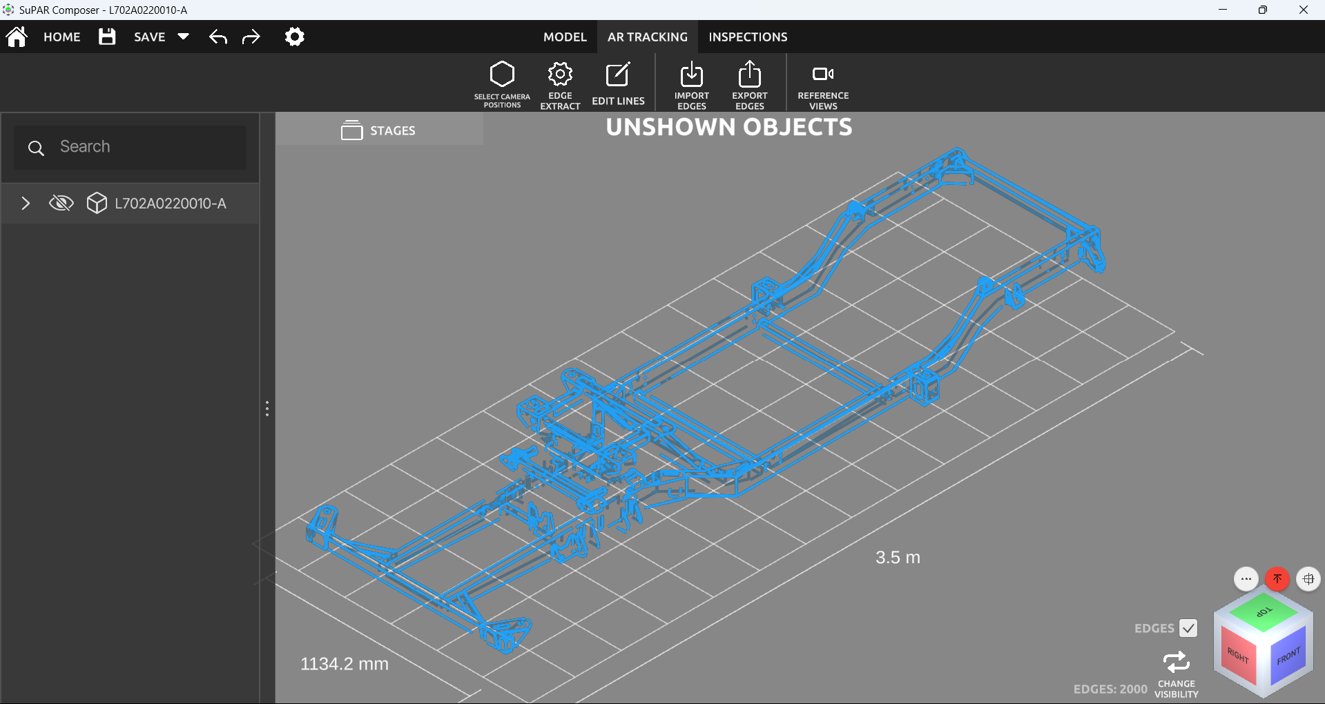
- Edges Count: Shows the number of extracted edges.
- Edges: Hide the CAD model and show only the edges.
- Change Visibility: Show hidden objects and edges together.
Recommended settings
Adding more tracking edges improves tracking for longer parts and increases stability.
| Part size | Render Resolution | Max Edge Count | View Count |
|---|---|---|---|
| Up to 2 m | 4096 | 2000 | 10 |
| 2 m – 8 m | 8192 | 3000 | 20 |
| 8 m – 20 m | 8192 | 4000 | 25 |
Parts longer than 20 m should be split into two sections.
Append and isolate
- Append: Extract the edges of the selected parts without removing the existing edges. Useful for parts with few or no edges. It cannot extract more edges than the maximum allowed for the part.
- Isolate Selected Parts: Extract the edges of only the selected parts. This makes it possible to extract edges for parts that are not visible from the outside, such as a part inside a box. Existing edges are removed and only the edges of the selected parts are extracted — combine it with Append to keep the existing edges.
Edit lines
Manually add or delete the edges to be tracked.
- Edit Lines: Add edges node by node on the part with the mouse while holding Shift. Delete an existing edge with the mouse while holding Ctrl.
- Select: Select the edges to be deleted with the mouse while holding Shift.
- Remove: Delete the selected edges.
Import and export edges
- Import Edges: Import extracted edges from an
AROBJfile. The positions of the parts must match the edges to be imported; if a transformation has been applied to the parts, the edges and parts will not match. - Export Edges: Export the extracted edges as an
AROBJfile.
Reference views
Reference views are used in the SuPAR App while superimposing the CAD model onto the actual part (see Open Project in the App).
- Click Reference View in the AR Tracking tab.
- Adjust the view to the desired reference image.
- Press Add Reference View.
The reference images appear on the left side of the ghost model in the SuPAR App.
Interior edge extractor
Create an edge extractor for identifying interior edges in the model. Multiple cameras can be added by clicking Create Interior Edge Extractor.
-
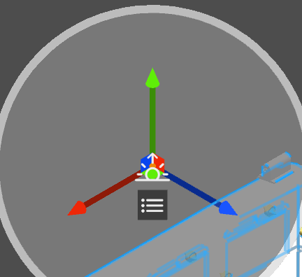
The camera gizmo is dynamic: move it with the green, red and blue axis arrows and squares by drag and drop.
-
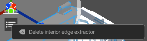
The interior edge extractor can be deleted with the button below the gizmo.
-
The number of cameras can be changed from Edge Extract → View Count. The camera count changes the number of created edges.